Nodes
A node executes a specific action and returns a result. The entire geometry creation process in BeeGraphy relies on nodes connected together on the canvas.
Anatomy of a node
Every node shares the same layout - a name, an icon, a management menu, and ports along either side. Inputs sit on the left and outputs on the right, so data always flows in one consistent direction across the canvas.
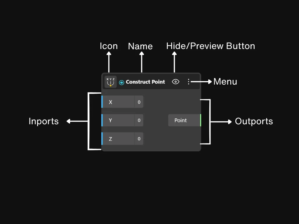
Name · Icon · Menu · Inputs · Outputs
Names and icons
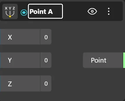
Every node carries a name and an icon that hint at what it does. The name is editable - rename it to anything meaningful for your graph. Renaming never changes the node's behaviour.
Node menu
Each node has a management menu. Open it from the ⋮ icon on the node header, or by right-clicking anywhere on the node itself. The same menu appears either way.
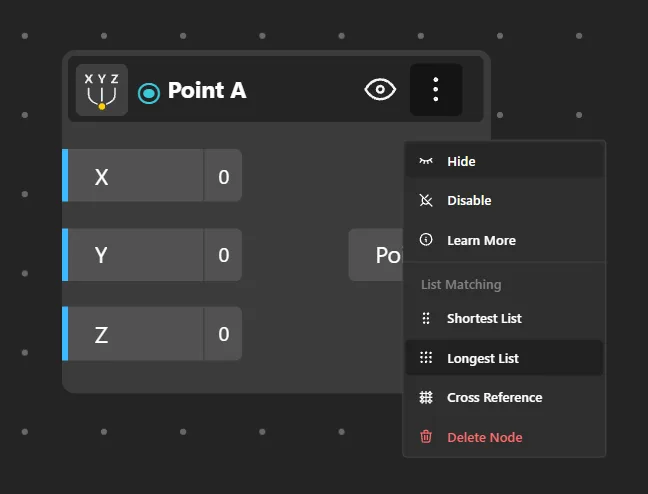
Hide
Toggle 3D preview
Disable
Pause computation
Learn More
Open node reference
Delete Node
Remove (Del key)
List Matching
Shortest List
Trim longer to match
Longest List
Extend shorter to match
Cross Reference
All pairings (A × B)
Input & output ports
Inputs sit on the left of the node and receive values; outputs sit on the right and pass results forward. Each port is coloured by data type and carries a label describing the value it expects. Many inputs accept a default value that you can set directly on the port.
Node states
A node's appearance tells you what it is doing. There are four states to recognise.
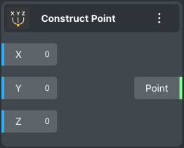
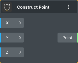
Working
Default look - computing and passing data through.
Selected
A coloured outline shows the node is active for editing.
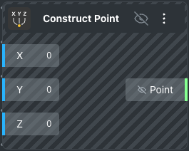
Hidden
Still runs, but its geometry is kept out of the 3D view.
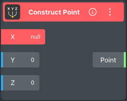
Error
Something went wrong - the node cannot produce a result.
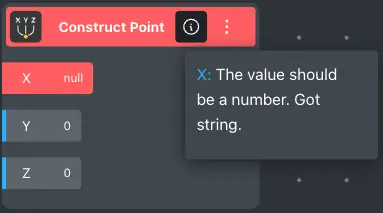
Inspecting an error
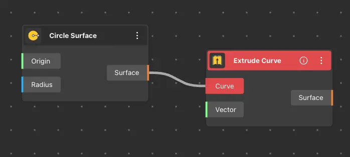
When a node is in the error state, click the info button on it to open a diagnostic panel. The panel explains what went wrong and flags the offending node in red so you can trace it back through the graph.
Ports
Ports are how nodes exchange data. Each port carries a specific data type and its colour tells you what it expects.
Drag a wire from an output port into an input port to connect two nodes. If the two ports carry different types, the connection is rejected and the input port turns red to flag the mismatch.
Multiple connections
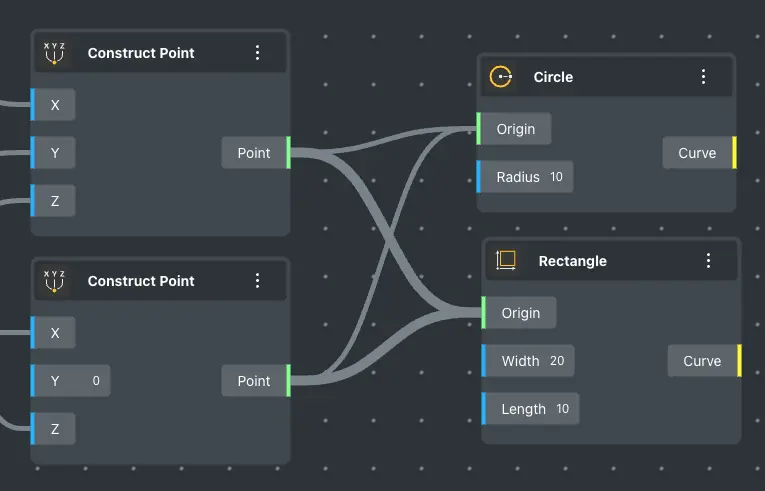
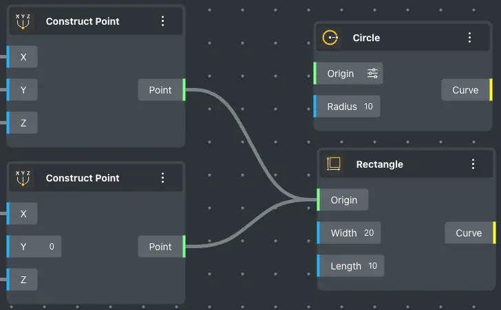
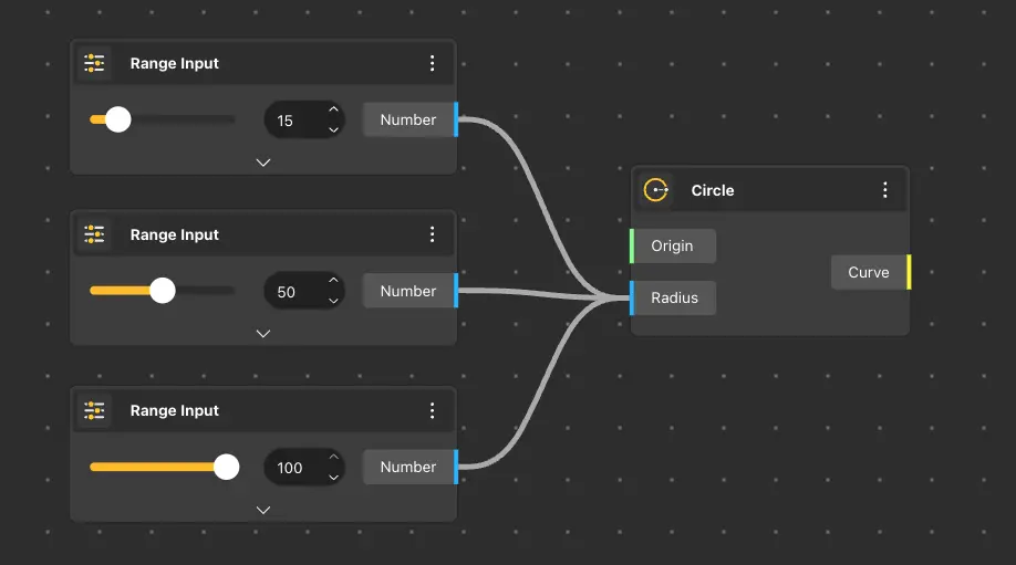
A single input port can receive more than one wire. The inputs are processed in the order they were connected. To add another wire to an already-connected port, either hold Shift while dragging the new wire in, or drag from the input back out to the output.
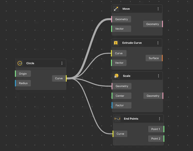
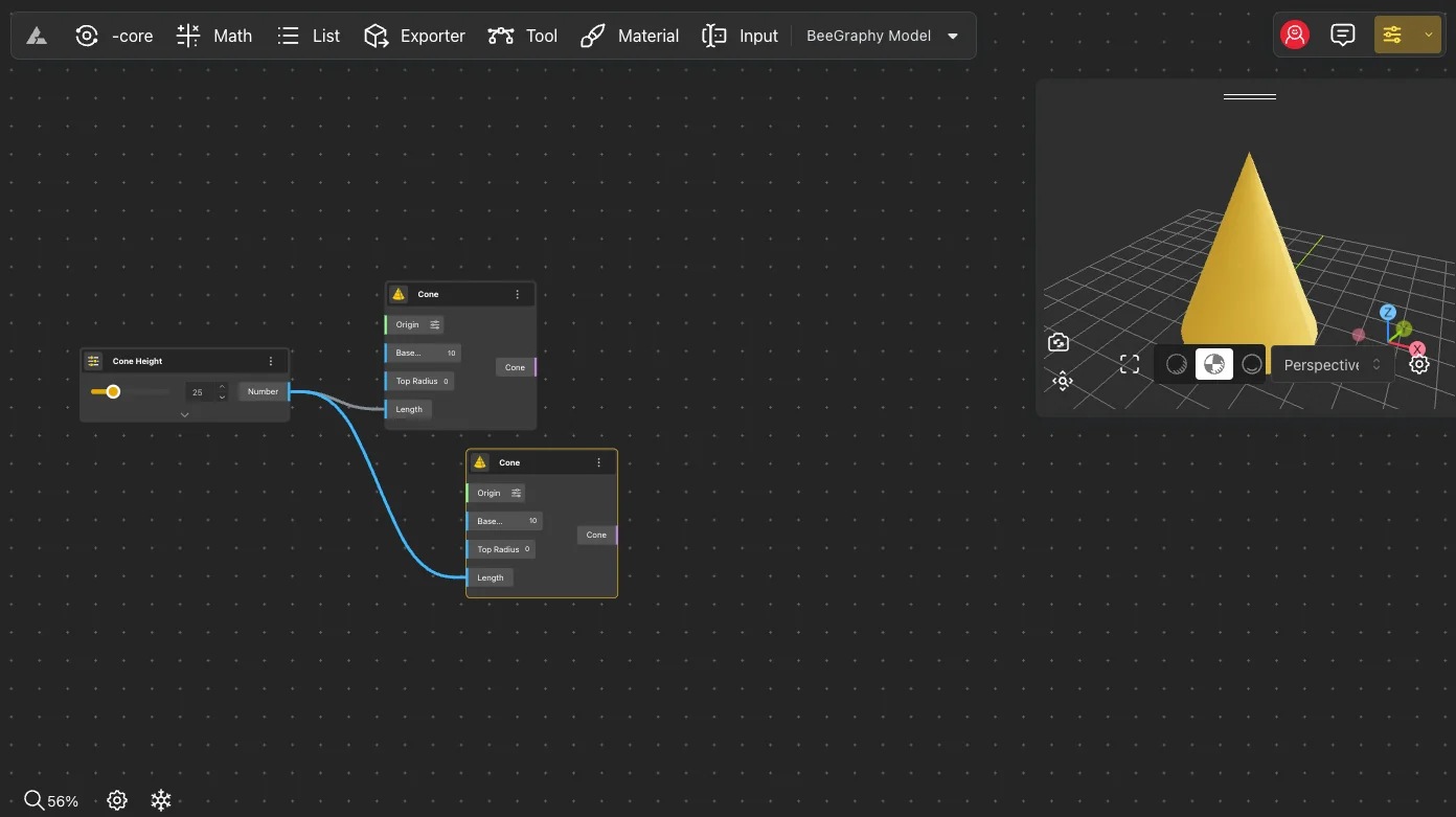
An output port has no limit - a single output can feed any number of downstream nodes at once.
Port menu
Left-click any port to open a small inspector showing its name, data type, description, and current value.
When a port holds more than one connection, use Move Above and Move Below in the inspector to reorder them - processing order follows this stacking. Output ports of nodes that can render to the 3D view include an extra toggle in their inspector that switches the node's preview between Show and Hide.
Node in workspace
Move nodes around the canvas to keep a graph readable.
To reposition a node, press and hold the left mouse button on it and drag to the spot you want. A single click selects the node - and if it outputs geometry, the matching shape lights up in the 3D view so you can see what it produces.
Connections
Wires carry data between nodes. Output goes in, input comes out the other side - always from left to right.
Input ports live on the left of every node and output ports on the right. When an input holds multiple wires, they are evaluated in the order they were connected.
Creating a connection
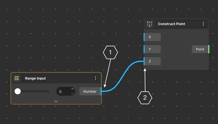
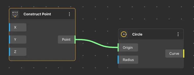
Press and hold the left mouse button on an output port, drag across the canvas, and release over the input port you want to feed. The wire snaps into place once the types match.
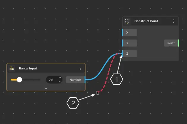
Disconnecting
Two quick ways to remove a wire:
- Hold Ctrl and drag the wire off the port it was sitting on.
- Or hold Ctrl and left-click directly on the port to drop its connection.
Transferring & duplicating wires
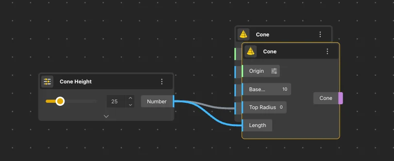
You don't always need to rewire from scratch. You can lift existing wires off one port and drop them on another, or copy them to run both.
Transfer
Hold Cmd/Ctrl+Shift and drag - the wires move to the new port, leaving the old port empty.
Duplicate
Hold Cmd/Ctrl+Shift+Alt and drag - the wires are copied onto the new port while the originals stay in place.
Selection
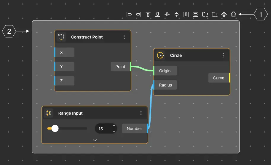
Pick one node or many, then align and tidy them from the floating toolbar that appears.
Three ways to select multiple nodes at once:
- Left → right marquee: only nodes fully enclosed by the selection box are picked up.
- Right → left marquee: any node the box touches is picked up, even partially.
- Shift + click: add individual nodes to the current selection one by one.
To drop a node from the selection, hold Ctrl and left-click on it. You can also drag a marquee (in either direction) back over the nodes you want to remove.
Arrangement tools
When several nodes are selected, a small toolbar appears above the selection. It offers alignment, distribution, and grouping actions:
- Align to the left, right, top, or bottom edge of the selection.
- Align horizontally or orthogonally to the centre.
- Distribute the nodes evenly along the horizontal or vertical axis.
- Wrap into a group, ungroup, turn into a reusable component, or delete.
Copy
Two ways to duplicate nodes - both preserve the wires between the copied nodes.
Shortcut: select the nodes and press Ctrl/Cmd+C to copy, then Ctrl/Cmd+V to paste the duplicates back on the canvas.
Alt-drag: with the nodes selected, hold Alt and left-drag. Release the mouse wherever you want the copies to land.
Groups
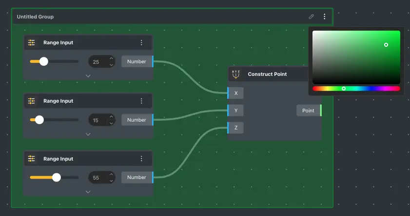
Bundle related nodes together under a name and colour so the graph stays legible as it grows.
Creating a group
Select the nodes you want to keep together and press Ctrl+G. A coloured frame wraps them and an editable title appears at the top - click it to rename.
The group menu
Every group has its own menu, opened by right-clicking anywhere on the group frame. From here you can recolour, hide, ungroup, turn the bundle into a reusable component, or delete it outright.

Hide
Stops every node in the group from rendering to the 3D view at once.
Ungroup
Removes only the frame - the nodes themselves stay on the canvas.
Create Component
Turns the grouped nodes into a reusable component you can drop elsewhere.
Delete
Removes the group and every node inside it.
Colors
Opens the colour picker with preset tints to tell groups apart at a glance.
Adding nodes to an existing group
Select the nodes you want to add, then right-click on the group and choose Add to group. To take a node back out, select it and use Remove from group from the same menu.
Moving and combining
Drag a group's frame with the left mouse button and every node inside moves with it. To fold two or more groups into one bigger group, select them all and press Ctrl+G again.